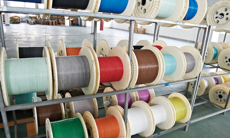
Manufacturing Process
Home » About Us » Our Capacity » Manufacturing Process

Step 1: Preparation and Purification of Fiber Optic Raw Materials.

1. The quality of fiber optic depends to a large extent on the purity of raw materials. The chemical reagents used as raw materials should be strictly purified, and the content of metal impurities should be less than several ppb, hydrogen compounds should be less than 1ppm.

2. The manufacturing of fiber optic should be carried out in the environment of purification and constant temperature, and the processes of fiber optic Core-rod , wire drawing and measurement should be carried out in the purification workshop of grade 10000 or above.

3. The stability of fiber optic quality depends on the stability of processing parameters. The preparation of fiber optic not only needs a set of precision production equipment and control system, but also it is especially important to maintain the stability of processing parameters for a long time. It must be equipped with a complete set of facilities and devices for detecting and correcting the operating parameters of various components of fiber optic processing equipment.

Step 2: Fiber Optic Core-rod Melting and Surface Treatment.

1. At present, there are four most mature technologies:
The Outside Vaper Deposition method, referred to as OVD (OVD-Outside Vaper Deposition)), was successfully developed by Corning Company in 1974 and fully operated in 1980.
The Inside Chemical Vaper Deposition method, referred to as MCVD (MCVD-Modified Chemical Vaper Deposition)), was developed by Alcatel Company in 1974.
The Vaper Axial Deposition method, referred to as VAD method (VAD-Vaper Axial Deposition)), was developed by NTT Company of Japan in 1977.
Microwave Plasma Chemical Vaper Deposition, abbreviated as PCVD (PCVD-Plasma Chemical Vaper Deposition)), was developed by Philips Company in the Netherlands.

2. At present, there are five main methods for surface treatment of fiber optic core-rods. They are:
(1)Cleaning the surface of Core-rod with organic solvents such as Etoh,Meoh, acetone and MEK.
(2) Etching Core-rod with acid solution.
(3)Flame polishing Core-rod .
(4)The Core-rod is cleaned with organic solvent and then further polished by flame.
(5)After cleaning with organic solvent, the Core-rod after acid etching is further treated by flame polishing.

3. Quality inspection of fiber optic Core-rod.
The quality of fiber optic Core-rod plays a decisive role in the quality of fiber optic and optical cables. there are three main aspects to detect the quality of Core-rods: (1) inspection of various defects in the memory of Core-rods; (2) detection of geometric parameters of Core-rods; (3) testing of refractive index distribution.

Step 3: Wire Drawing and Primary Coating Process.

1. Fiber optic wire drawing refers to the technological operation process in which the prepared fiber optic Core-rod (rod) is heated and melted by some kind of heating equipment to produce a slight fiber optic whose diameter meets the requirements, and ensures that the core/coating diameter ratio and refractive index distribution of the fiber optic remain unchanged. In the process of wire drawing operation, the most important technology is how to ensure that the fiber optic surface is not damaged and how to correctly control the core / coating outer diameter size and refractive index distribution. If the surface of the fiber optic is damaged, it will affect the mechanical strength and service life of the fiber optic, and the outer diameter will fluctuate, because the imperfect structure will not only cause the scattering loss of the fiber optic waveguide, but also increase the connection loss when the fiber optic is connected. Therefore, when controlling the fiber drawing process, various process parameters and conditions must be kept stabilized. The Primary Coating process is to coat the drawn bare fiber optic with a coating material with high elastic modulus, which can protect the drawn fiber optic from damage, improve its mechanical strength and reduce the attenuation. In terms of technology, Primary Coating and wire drawing are two independent process steps, but in actual production, Primary Coating and wire drawing are completed at one time on the same production line.
The wire drawing machine of fiber optic Core-rod consists of five basic parts: (1) fiber optic Core-rod feeding system; (2) heating system; (3) wire drawing mechanism; (4) parameter control system; (5) water cooling and atmosphere
 protection and control system. The precise matching among the five parts forms a complete wire drawing process. The specific mechanical and electrical equipment and systems include: mechanical system wire drawing tower, rod feeding and centering system, heating furnace, laser diameter gauge, traction device, water and gas pipeline system, electrical part rod feeding control and centering control system, heating furnace control system, outer diameter measurement and control system, traction control system, cooling water and protective atmosphere control system, man-machine interface, PLC signal processing system and so on.

2.The reason why the Primary Coating process of fiber optic is called "Primary Coating" is relative to the Secondary Coating. Primary Coating is the most direct protection of fiber optic cable, so it is particularly important.
The number of layers of a coating is generally two layers: pre-coating and tight buffer layer.
Considering the thickness of the coating:the thicker the coating is, the better is if only considering the mechanical strength. If the transmission characteristics of the fiber optic are taken into account, the coating is too thick, which will not only produce micro-bending when bending, stretching and temperature changes. At the same time, it will also become the main reason for the increase of fiber optic loss. In addition, the mechanical characteristics of the coating material also seriously affect the transmission characteristics of the fiber optic.

Primary Coating process.
According to the different coating equipment used, there are three different optional processes: 1) wick coating; 2) guide tube coater coating; 3) automatic centering coater coating. At present, the third process is the most commonly used.

Step 4: Fiber Optic Cable Tension Sorting and Coloring Process.

1. Tension Sorting.
After coating and curing, the fiber optic can be in direct contact with the mechanical surface. In order to ensure that the fiber optic has a minimum strength and meet the mechanical performance requirements of plastic sheath, cabling, laying, transportation and use, 100% tension Sorting of a coated fiber optic must be carried out before the cable is completed. There are two kinds of tension Sorting methods: online Sorting and non-online Sorting. The so-called on-line tension Sorting means that the tension Sorting is completed synchronously on the fiber optic drawing and coating production line. Due to the short curing time of the fiber optic coating, the measured fiber optic strength will be affected to a certain extent. Independent fiber optic tension Sorting is completed on special tension Sorting  equipment, and in general, independent fiber optic tension Sorting is used for fiber optic tension Sorting .

2. Fiber Optic Coloring Process.

Fiber optic coloring is a process in which ink of a certain color is coated on the surface of the fiber optic and solidified to maintain strong adhesion.

Coloring method: in the past, the tightly sheathed fiber optic was coloured after the Primary Coating or the pigment was added to the Secondary Coating material, while the ribbon fiber was colored before the ribbon was formed, and the loose tube fiber optic was colored after the Primary Coating. Nowadays, no matter what kind of fiber optic, the coloring process is usually used after a Primary Coating.

Requirements: the requirement of the coloring process is that the color of the colored fiber optic should be bright and easy to distinguish, the color layer is not easy to fall off, and the compatibility with the fiber optic water blocking filling gel is good, and the coloring layer is uniform to avoid fiber breakage.

Methods: there are two common coloring methods: online coloring and independent coloring. On-line coloring refers to a method of simultaneous coloring in the process of wire drawing and Primary Coating, while independent coloring is a method of independent coloring on the coated fiber optic by using special coloring equipment. at present, more coloring is done by using the latter method.

Step 5: Secondary Coating or Plastic Coating of Fiber Optic.

The Secondary Coating process of fiber optic, sometimes called plastic coating process, is the second layer protection operation of fiber optic after Primary Coating and coloring. After Primary Coating, the mechanical strength of the fiber optic is still low, which can not be used without further enhancement. As we all know, fiber optic is inevitably affected by external tensile stress, compressive stress or shear force in practical use. External force will not only affect the transmission performance of fiber optic, but also have a greater impact on its mechanical properties. At the same time, when the external ambient temperature changes, the transmission characteristics of fiber optic will also be affected due to the poor temperature characteristics of the fiber optic coated once. To this end, in order to complete the fiber optic in the cable, extrusion sheath and other post-sequence processes as well as transportation. In order to meet the requirements of its transmission and mechanical characteristics in practical use, the fiber optic after Primary Coating and coloring must be further protected to keep the fiber optic sufficient mechanical strength and better temperature transmission characteristics. The purpose of the plastic covering operation is to protect the Primary Coating of the fiber optic, increase the mechanical strength of the fiber optic, and improve the transmission and temperature characteristics of the fiber optic. The Plastic Coating process operation can be divided into three process modes: Loose Coating, Tight Coating and belt forming. The Loose Coating process is that on the outer surface of the Primary Coating fiber optic, there is a Loose Coating buffer plastic tube with a certain diameter and thickness, referred to as the Loose Coating, and the Primary Coating fiber optic can move freely in the loose buffer plastic tube. the Loose Coating is filled with water-blocking oil filling gel. According to the shape of the fiber optic structure in the loose tube, it can be divided into two types: the general loose-coating fiber optic is plastic, at this time, the fiber optic in the tube can be one or more than one bundle. The fiber optic belt is loosely coated with plastic, and the fiber optic inside the Loose Coating is fiber optic ribbon; tight coated fiber optic, as its name implies, tightly coated the outer layer of the fiber optic after the Primary Coating with a layer of polymer such as concentric acrylate, nylon or polyethylene. The Secondary Coating is closely attached to the Primary Coating, and the fiber optic cannot move freely in the Secondary Coating. The so-called fiber optic ribbon is the technological operation process in which several colored fibers, such as 2X2, 4X4, 6X6, 8X8, 12X12, 16X16, 24X24, are arranged in parallel according to a certain law, and are bonded into ribbon fiber optics with polyethylene and other polymer materials, and the technological process of arrangement and bonding is called ribbon formation, also known as banding.

Step 6: Fiber Optic Cable Core Manufacturing Process (Cable Forming Process).

Fiber optic cabling is a process of stranding several tight-coated fiber optics, Loose Coated fiber optics, fiber optic bundles or ribbon fiber optics with reinforcements, water-blocking materials, bandages and other elements into a central tubular, layer stranded or framed optical cable core according to certain rules. The purpose of the cable is to obtain a structurally stable optical cable core, so that the extruded optical cable has better mechanical properties and temperature characteristics, such as tensile resistance, compression resistance, bending resistance, torsion resistance and impact resistance, and has the minimum geometric volume. At the same time, it can improve the compression strain caused by the micro-bending of the fiber optic caused by external force and the change of ambient temperature, and maintain the inherent excellent transmission characteristics of the fiber optic. The cable forming process requires that the optical cable core must have excellent mechanical properties and meet the requirements of various conditions and methods of transportation, storage, laying and use under different environmental conditions. At the same time, the original fiber optic transmission characteristics must be maintained after the cable is completed, and the temperature characteristics must be greatly improved. According to the different cable core structure, the cable forming process can be divided into: central tube cable core cable forming process, layer stranded cable core cable forming process and skeleton slot cable core cable forming process.

1. Cable Forming Technology of Layer Stranded Optical Cable.
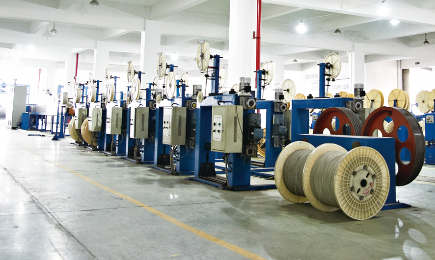
层绞光缆生产线 Production line of layer-stranded cables 01
The layer stranded structure takes the cable core of Loose Coated fiber optic, reinforcement unit, water blocking material and bandaging tape or other structures as basic unit elements (such as one-layer or multi-layer skeleton slot ribbon fiber optic cable core unit). A technological operation process in which the cable is stranded by a stranding machine. Its process basically follows the cable production process, in the three cable operations, it is the most mature technology. According to the different stranding methods, it can be divided into SZ stranding (also called left and right stranding) and spiral stranding (also known as unidirectional stranding, S stranding or Z stranding). The performance of the optical cable produced by the two processes is similar, but the cable forming technology and equipment are very different. In the process of stranding, the length between the loose fiber and the optical cable must form a certain excess length, and the method to obtain this excess length is to use the SZ stranding or spiral stranding of the fiber optic.

1.1)SZ stranding process.
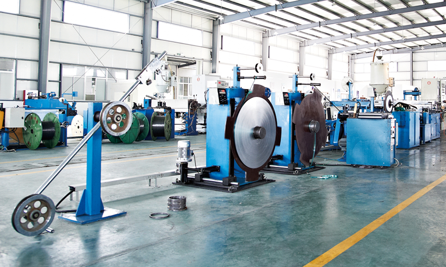
蝶形光缆生产线Butterfly cable production line
The so-called SZ stranding means that when the stranding element reaches the specified number of turns in S direction (or Z direction) along the longitudinal axis of the optical cable, and then reverses the same number of turns in Z direction (or S direction), the stranding form of another stranding cycle is restarted. At the commutation point, the stranded element is parallel to the axial direction of the optical cable. Because the stranded element has a certain hardness, in order to keep the stranded element in a suitable stranded position during commutation, the stranded element of the SZ stranded core must be wrapped and fixed, and the polyethylene filled rope must be filled in the gap of the stranded element to make the structure of the stranded unit more stable, and to fill the optical cable water repellent filling gel (cable filling gel for short) to absorb the external immersed water. The realization of SZ stranding process is completed by a SZ stranding machine. The production speed of SZ stranding is fast and the production efficiency is high. For the fiber optic in each stranded unit, due to the stranding in two directions, the deformation of loose-tube fiber optic caused by stranding is reduced to a minimum and can be compensated.
In order to control the quality of products. It is very important to ensure that the residual length of the cable core is normal and the attenuation meets the requirements. Therefore, in the production process, the process parameters such as cable pitch, yarn binding pitch, yarn binding tension, laying-off tension and reinforcing tension must be strictly controlled.
The bandaging belt can play the role of fixing the cable core, such as using the water blocking belt as the Jacketing belt, which also has the function of absorbing water, the general binding pitch of the bandaging belt must ensure that the cable core is not loose. Yarn-binding tension is a very important parameter, which is closely related to the attenuation of fiber optic and should not be too large or too small. If the tension is too small, it is easy to cause the yarn to be loose, the cable core to be fixed and loose, and it is easy to cause cable breaking accident when the sheath is extruded in the next process; while the tension is too high, there will be the phenomenon of bandaging flat fiber optic bushing. the primary colored fiber optic in the casing is subjected to stress, resulting in bending attenuation and quality accident.

Step7: Extrusion Technology of Optical Cable Integrated Jactketing.

护套生产线 optical cable sheathing of production line
In order to protect the fiber optic cable core from external mechanical, thermochemical, moisture and biological gnawing, the outer core of the optical cable must be jacketed, or even protected by an external sheath. only in this way can we more effectively protect the normal operation and service life requirements of the fiber optic. The production process of optical cable integrated sheath must be able to ensure the production of qualified sheath in accordance with the following requirements:
(1) Completely Sealed. For optical cable, it is very important to prevent the invasion of moisture or moisture that may affect the performance of optical cable and eventually lead to the failure of optical cable. Therefore, the production of jackets must be completely free of bubbles, pinholes and welds.
(2) There are accurate size, good concentricity, smooth surface, especially the inner surface of the jacket.
(3) In order to reduce the connection point of optical cable, the production mode of long continuous length of optical cable should be realized as far as possible. At present, the typical connection length of optical cable is 5km, which can reach 6~7Km or even longer if there are special requirements.
(4) The cable core shall not be damaged in the process of production.

1 Water Blocking Technology of Optical Cable.
With the continuous development of fiber optic core and fiber optic cable manufacturing technology and materials, the water resistance technology of optical cable has developed from the earliest gas pressurization water resistance to the current stage of filling water resistance Gel and water absorption expansion materials, and the level of water resistance technology has been greatly improved and developed.
(1) Filling of Gel.
Fiber filling gel, cable filling gel or sheath Gel filling is usually filled with special Gel filling equipment: Gel filling machine.We take cable gel filling as an example to briefly discusses. The basic filling principle is to use a high-pressure oil pump to pump the Gel into a specific container, which adopts a reflux device, and an Gel mold with a size matching the cable core is installed at the outlet of the container for two purposes: one is to ensure the surface of the cable core is round; the other is to control the amount of Gel. When the Gel is insufficient or uneven, it will lead to the uneven outer surface of the optical cable sheath. In addition, too much Gel will produce bubbles and necks during the extrusion of the sheath. In the production process, it is necessary to ensure that the Gel is filled evenly, filled and does not leak.
(2) Dry Water Blocking Process.
In order to ensure the longitudinal water resistance of optical cable, in addition to gel filling, there is also a dry water resistance process. The dry water resistance process can be divided into two structures: "full dry" and "semi-dry".

2 Longitudinal Jacketing Process.
The quality of the longitudinal Jacketing technology directly affects the surface quality and mechanical properties of the optical cable, so the quality of the longitudinal Jacketing is the primary problem of the sheath technology. The longitudinal Jacketing process includes water barrier longitudinal Jacketing, steel (aluminum) plastic composite belt rolling, Core-rod forming, lapping and shaping. In order to ensure that there is no water seepage in the gap between the cable core and the wrinkled steel (aluminum) plastic composite belt, the longitudinal Jacketing process of the water barrier is adopted. The thickness of the water barrier is generally 0.25mm and the width is designed according to the outer diameter of the cable core to ensure that there is an overlap area of 3~5mm after the completion of the longitudinal Jacketing of the cable core. The longitudinal rolling device of steel strip / aluminum strip is composed of a rolling machine and a longitudinal Jacketing machine.

3 Plastic Extrusion Process.
The quality of the plastic sheath of optical cable is related to many factors, such as the quality of the plastic material itself, the performance of the extruder, the extrusion temperature, the tension, the traction speed, the cooling mode of the plastic after extrusion, the die design of the machine head and so on.
(1) Plastic Extrusion mould.
The die used in the production of optical cable sheath extrusion, including die core and die sleeve, is mainly in three forms: extrusion type, extrusion tube type and semi-extrusion tube type. The structure of the three kinds of mould is basically the same, and the only difference lies in whether there is a tubular bearing diameter part at the front end of the die core or the relative position between the tubular bearing diameter part and the die sleeve is different.
(2) Extrusion die.
There is no tubular bearing diameter part of the extruded die core, and the die core is shrunk behind the die sleeve diameter. The molten plastic is finally shaped by pressure through the mold sleeve, and the structure of the extruded plastic layer is compact and the appearance is smooth. The angle between the die core and the die sleeve determines the material flow pressure, which affects the quality of the plastic layer and the extruded optical cable. The disadvantage is that the glue discharge speed is slow, the eccentricity adjustment is difficult, and the thickness is not easy to control.
(3) Extruded Tube Die.
Extruded tube type is also called sleeve type die. The die core has a tubular bearing diameter part, and the extrusion method in which the die core end protrudes the die sleeve end face or is flat with the die sleeve end face is called extruding tube type. In pipe extrusion, due to the existence of the tubular diameter part of the die core, the plastic is not directly pressed on the cable core, but moves forward along the tubular diameter part, forming a tube at first, and then stretching and then Jacketing on the optical cable core.
(4) Semi-Extruded Tube Die.
The semi-extruded tube die core has 5mm left and right tubular bearing part, which is between the extruding type and the drawing type, and the die core mouth end is basically in the middle of the flatness (bearing diameter) of the die sleeve. In semi-extruded tube extrusion, because the die core is shrunk behind the die sleeve diameter, the molten plastic is shaped by a certain pressure through the die sleeve, and this pressure is much smaller than that of the extrusion type; because in the die sleeve diameter, there is a section of die core tubular bearing diameter length, so it retains some characteristics of the drawing tube die. The molten plastic is pulled out along the tube and then coated on the cable core. The semi-extruded tube die combines the characteristics of extrusion type and extrusion type, and the performance is between the two. It is widely adopted in the sheath technology of ADSS optical cable and some special products.

4 Armored Technology.
The armour technology of optical cable is a kind of protective operation process adopted in order to increase the tensile and compressive strength of optical cable and install metal structure layer. The armor layer is located between the inner and outer sheath of the optical cable. There are generally two kinds of armoring materials and methods: steel wire armoring and steel tape armoring. There are two kinds of armoring technology: longitudinal Jacketing process and winding process. There are mainly two kinds of optical cable armour equipment: steel wire armour machine and steel strip armour machine.
(1) Steel Wire Armoring.
Generally speaking, steel wire armoring is not needed for ordinary directly buried and pipeline optical cables, and steel wire armoring must be used for submarine optical cables.
(2) Steel Tape Armoring.
Most of the steel belts for armour are phosphorus-plated steel strips, and there are also galvanized steel strips. The number, thickness and width of steel strip are selected according to the diameter of optical cable before armoring.

5 Integrated Jacketing Production Line.
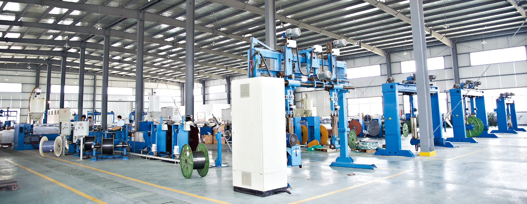
护套生产车间 Jacketing workshop
The integrated Jacketing production line and equipment is the special production line equipment for the last processing process in the manufacturing process of optical cable. This process can be subdivided into the following steps.
Cable core release, Cable core water resistance treatment,Aluminum-plastic belt / steel-plastic belt longitudinal Jacketing (or extruded plastic sheath), armoring, Plastic extrusion,Cooling, Printing, Spark monitoring,Take-up cable.
If you would like to have a question then get in touch today, we are ready to assist 24/7.
We welcome your cooperation and we will develop with you.

 Factory-direct Connectivity Solutions.
 High quality, Competitive Price.
 Custom-tailored solutions.
 Problem-solving approach.

QUICK LINKS

SUPPORT

WHAT'S NEW

CONTACT INFO

  Info@litangcables.com
 
+86-18888978088
      +86-571-87922289
   +86-18888978088
 No.557, Gaotang Road, GuaLi Town, Xiaoshan district, Hangzhou City, Zhejiang Province, China.
Leave a Message
Contact us
Copyrights 2020 Zhejiang Litang Cable Co., Ltd. All rights reserved. Sitemap